
 Home
Home A-frame for M-37?
Moderators: Cal_Gary, T. Highway, Monkey Man, robi

A-frame for M-37?
I've been told that they made an A-frame that attached to the front bumper of the M-37 for lifting heavy objects. Does anyone know the dimensions or capacity or have a picture of one? I've seen one original A-frame on a Deuce and half and it was surprisingly small. I'd guess it was only about 8 foot tall. I've seen much bigger home made ones that worked great on the Deuce and I'm wondering if the "small" 8? footer was originally made for an M-37. I need to make something like that for my M-37 and I'm looking any guidance on how big I should make it and/or what the weight capacity should be limited to.

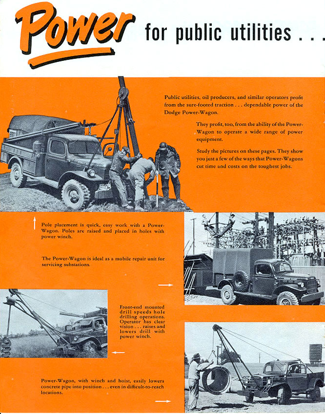
They're called "gin poles" and were used for all kinds of light lifting chores, such as loading/unloading cargo when a crane or a forklift was either not available or not practical for the task at hand. Load limits were pretty low, figuratively speaking, for two reasons. (1) Too much weight would buckle the tubes, and (2) if the tubes held, you could lift your back wheels off the ground.
"PER ARDUA AD ITER"

Joe is this what your looking for ?http://www.lov2xlr8.no/brochures/dodge/ ... lder/8.jpg
1954 M37 WO/W
1969 M101A1
1967 M416
1969 M101A1
1967 M416
I used a set on my WC and have also had them on an M37. Another problem is with heavy loads that Lifer didn't mention is the front springs will flatten out and possibly break. Lifting heavy loads using gin poles will result in problems and that's why Lifer wrote they " were used for all kinds of light lifting chores ".
Taken years ago, this is a shot of setting a recently restored cab on my M37 frame while my son guides it into place.
Click on thumbnail

Taken years ago, this is a shot of setting a recently restored cab on my M37 frame while my son guides it into place.
Click on thumbnail
Carter
Life Member:
Delta, Peach Bottom Fish & Game Assn.
Life Member:
Delta, Peach Bottom Fish & Game Assn.
Carter and Sal,
yes that's exactly what I had in mind. Anything that could lift a cab is probably strong enough for me. I realize that overloading the springs is a possibility. It's something that I'd have to watch for and block up the frame or bumper if necessary. Carter, do you remember how long your pipes were and what their id and od was? How did you attach them to the bumper and how heavy a chain did you use to support the rig? What did you attach the back of your chain to? It looks like it ran down the side of the truck instead of over it. I have a couple of 20' lengths of 2" od black iron well pipe that I was considering using. Not full length but perhaps 12'. A couple of people have suggested using U-joints from drive shafts to connect to the bumper so that the A-frame can move freely but they're not designed to take a thrust load and I don't think they would carry much of a load. I think I'm going to have to make some swivels out of heavy plate steel and pins.
FWIW My understanding is that a Gin pole is a single pole used to raise loads. Gin poles are usually used only to raise objects MOL straight up such as when erecting radio towers because they can't withstand the bending that cantilever loads cause. I plan on using two poles tied together at the top and supported by a guy wire (or chain) or two so I think A-frame is a more fitting description.
Official terminology and local nomenclatures often miss each other when the conversation is opened with folks outside the local circle.
The technical term for the two pole system is Shears. They are very often referred to as "A Frames", "Gin Poles" and "BiPods". They all represent the same pair of poles.
The Army rigging TM's and FM's are a good source of how to and correct name calling.
http://drum-runners.com/Mil%20-%20Rigging%205.pdf
Wes K
wsknettl@centurytel.net
54 M37, 66 M101, 45MB, 51 M38, 60 CJ5, 46 T3-C
MVPA 22099
Disclaimer: Any data posted is for general info only and may not be M37 specific or meet with the approval of some esteemed gurus.
wsknettl@centurytel.net
54 M37, 66 M101, 45MB, 51 M38, 60 CJ5, 46 T3-C
MVPA 22099
Disclaimer: Any data posted is for general info only and may not be M37 specific or meet with the approval of some esteemed gurus.
Thanks Wes for posting the manual pages. I never knew that's what the army called them, ok, shears it is and thanks again.
I looked for my shears that fit the M37 but I think they maybe at my buddy Ralphs place. I'll check. That I have or will find were telephone co. ones that came from a wrecked Power Wagon phone truck. They are not the ones I had on the front of my WC 52. One leg of the phone co. ones telescoped together mid length and was adjustable over a 3 foot range with a series of holes to pin the leg in place, leveling the rig when the truck was on a slope. Both ends of each pole had a connecting lug built in with a hole the size of a shackle bracket's one. The poles were 4" dia 1/4" thick and were about 8' long. Mounted on an M37 with the snatch block hanging down, the set-up would lift nearly 8'. When fitted to an M, the tail gate was removed and a length of 1/2" steel cable back staying the rig and load. I would bolt the legs securely but not torqued tight to the inside face of the shackle brackets mounts so the load was pushing against the mount, not pulling on it. You want compression on the connection, not tension to keep the legs together.
I'll get some pix once they are found , I'll email Ralph and ask if he has or has seen my shears, I'm sure he will think I've lost my mind and will possibly suggest I look in the desk drawer with the ruler and paper clips. He might not tell me he has them but later when I search a day or two just to mess with me a bit. He can be quite a cut-up when looking for shears.
Carter
Life Member:
Delta, Peach Bottom Fish & Game Assn.
Life Member:
Delta, Peach Bottom Fish & Game Assn.
-
Master Yota
- MSGT

- Posts: 828
- Joined: Sun Nov 15, 2009 11:50 am
- Location: Prince George BC Canada
- Contact:
No idea of the rating Joe, I' m sure the set would have caried a much heavier load than I was going to lift. The trucks front springs being the weak point I lifted stuff less thal 500#, including a set of precast concrete steps that I placed for a friend that were just under 500 at 480 which had the springs flattened out. Wont try that again but no harm done.
The top of the legs were connected with a an 8' long steel pin pushed through a lifting shackle and then through the shear leg top holes and fixed with washers and large cotter pins. This was something I made as I wasn't sure what orig. went there to connect the legs and cary the load.
The top of the legs were connected with a an 8' long steel pin pushed through a lifting shackle and then through the shear leg top holes and fixed with washers and large cotter pins. This was something I made as I wasn't sure what orig. went there to connect the legs and cary the load.
Carter
Life Member:
Delta, Peach Bottom Fish & Game Assn.
Life Member:
Delta, Peach Bottom Fish & Game Assn.
-
Master Yota
- MSGT
- Posts: 828
- Joined: Sun Nov 15, 2009 11:50 am
- Location: Prince George BC Canada
- Contact:
My M37 when I bought it had a pair of air bags installed in the front suspension along with the leafs (of course...) I'm wondering if they used the air bags to support some extra weight. I don't know if my M ever had a set of Shears attached to it, but it could be a logic reason behind the air bags being there...
Ray
1953 CDN. M37
1954 CDN. M152
1953 CDN. M37
1954 CDN. M152
18 April 10
Hello all -
I came across some data and pictures referring to what I had always called an 'A' frame. It was refered to as a Derrick kit and contained info saying the lift capacity was 1500lbs. I found it while researching Canadian M-37's and other early M-series equipment. I am going to assume that the US version was the same or very close to this Canadian kit. I've seen some home-made types that others have posted on different Dodge Power Wagon related sites, but never an official 100% ex-military surplus setup. I wonder how common these kits were since very little info seems to exist - let alone pictures of them put to use in service. Unfortunately I haven't figured out how to post pics of the sheet I scanned. If someone can give me a quick run down on the process I'll post the pics for all to have a look at. I would love to have a complete kit for mine, just to compliment the truck. Cheers.
19 April 10 - I've posted the pics in the Gallery under Craig Sparks - tried unsuccessfully to attach them here by the url....