

 Home
Home 

hello guys I am fixing the measuring system.
I've started with the sender, it was internally damaged and the floating element stick was broken. had to rebuilt the caption circuit and weld the stick back
it took me a lot of work but now seems to work as designed 15 to 87 ohms (specs: 10 F 90 E)
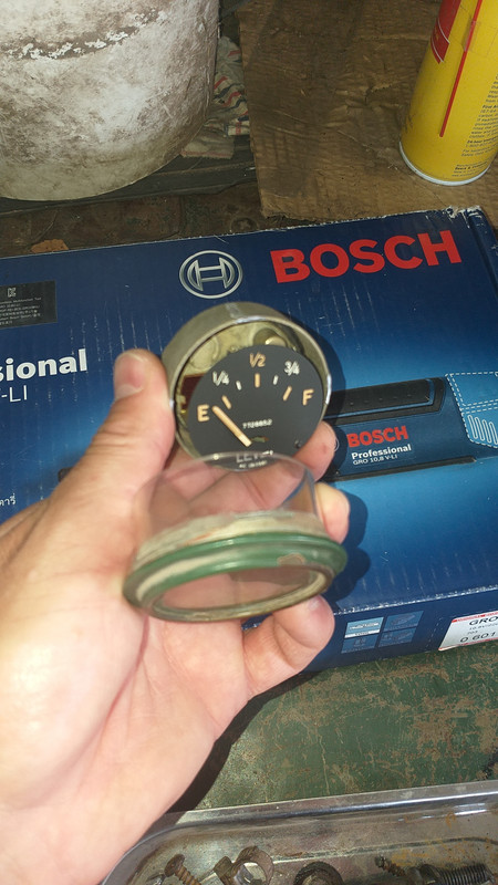
I've also opened the gauge as it is damaged too. but could not make it work. Actually it works opposite as expected. so i am stuck thinking how to solve it
is there any replacement?
I can share pictures if you want
fuel sender / gauge
Moderators: Cal_Gary, T. Highway, Monkey Man, robi

Re: fuel sender / gauge
No pun intended but gauges are "floating" around here and there. I might have a spare in the basement that I can try to dig up tomorrow.
Gary
Gary
Cal_Gary
1954 M37 W/W
MVPA Correspondent #28500
1954 M37 W/W
MVPA Correspondent #28500
Re: fuel sender / gauge
Sorry Vit I don't have the fuel gauge anywhere.
Gary
Gary
Cal_Gary
1954 M37 W/W
MVPA Correspondent #28500
1954 M37 W/W
MVPA Correspondent #28500

Re: fuel sender / gauge
Are you sure you have the correct gauge? They make gauges that read "0 empty / 90" full as well as "90 empty / 0 full".vit16 wrote:hello guys I am fixing the measuring system.
I've started with the sender, it was internally damaged and the floating element stick was broken. had to rebuilt the caption circuit and weld the stick back
it took me a lot of work but now seems to work as designed 15 to 87 ohms (specs: 10 F 90 E)
I've also opened the gauge as it is damaged too. but could not make it work. Actually it works opposite as expected. so i am stuck thinking how to solve it
is there any replacement?
I can share pictures if you want
This is a long shot - and I don't recall the details to know if an incorrect connection is possible, but: If you are certain the gauge is correct, is it possible you connected one of the wires to the wrong side of the variable resister in the sending unit when you were repairing it? The guts of the sending unit is a coil of resistive wire with a wiper that slides back and forth across that coil. One electrical connection is made at the wiper, the other to one end of the coil. The resistance through it is dependent on where on the coil the wiper sits. If you connected to the wrong end of that coil, resistance for full and empty will be backwards.
1951 M37 "Brutus" w/Winch and 251 engine
Re: fuel sender / gauge
thanks both guys.
I have restored the sender wipe so it works capturing the coil as designed but seems that the issue is that the gauge is not for that sender
very good info you are giving me. now I can reweld the floating to work in the opposite direction.
trust me I've tried with my brother every single configuration to make the gauge work opposite as I was. I have to modify much more inside the gauge than cutting the sender an weld it to work in the opposite way.
thanks now I can see a light in the tunnelend and it's not the train hahahh
Ronnie
Re: fuel sender / gauge
the sender soil connects one end this the gauge and the circuit shorts to ground using the wiper position so it only varieties resistance. the only way to make it works backwards is by welding the floating element in the other side. I have to remove it and modify it.
Re: fuel sender / gauge
sorry my corrector does what ever he wants...
Re: fuel sender / gauge
Adding some pictures you will like!!
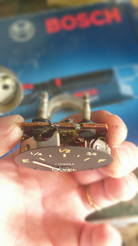
opened gauge with dremel:
I've cut the metal asuming I will weld it back
there was an open circuit there from the constant field coil (red, RH)
I soldered it back and works but backwards, and maybe I will have to add a certain amount of extra resistor to make it work as expected.
And here the sender
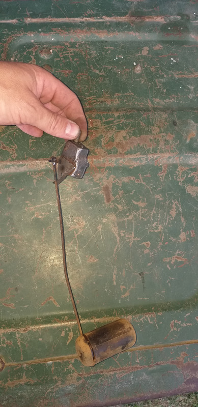
take a look at the wipe I have restored, it was almost follen. The circuit comes from the gauge and enters to the sender through the thread, that is only what you have, and the wipe, shorts the resistor to ground depending the fuel level.
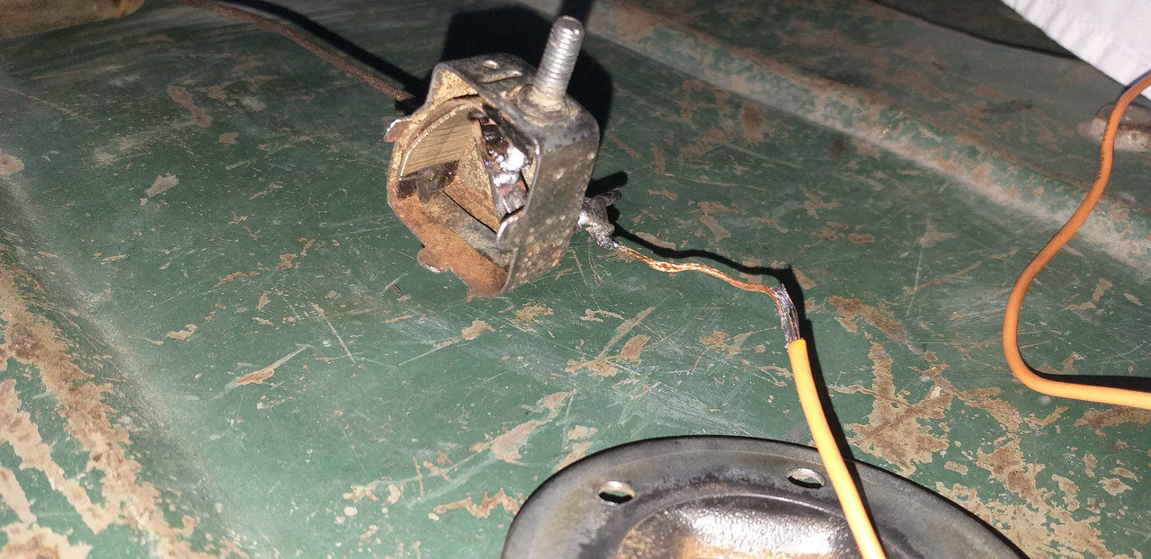
I have added an extra wire, that it is not original, but believe me that I don't want to have ground through the sender body (now clean but later rusted, and neither through the tank that it is suspended and I've added rubber to avoid painting damage, so where is the correct ground in the original design I don't know so I've added extra ground to avoid this possible fail.
Lastly and hope you like my description I will cut the sender wire and weld it in the other side to make it work backwards to have 10 ohms empty and 90 full.
It will be the easiest way to make them match.
If not, I would have to swap both little coils, and then I have to almost destroy the "iron" that aligns magnetically when gauge is energized and moves with the gauge needle. And that is very difficult to modify (i've tried hehehe)
ok will update in 7 days
opened gauge with dremel:
I've cut the metal asuming I will weld it back
there was an open circuit there from the constant field coil (red, RH)
I soldered it back and works but backwards, and maybe I will have to add a certain amount of extra resistor to make it work as expected.
And here the sender
take a look at the wipe I have restored, it was almost follen. The circuit comes from the gauge and enters to the sender through the thread, that is only what you have, and the wipe, shorts the resistor to ground depending the fuel level.
I have added an extra wire, that it is not original, but believe me that I don't want to have ground through the sender body (now clean but later rusted, and neither through the tank that it is suspended and I've added rubber to avoid painting damage, so where is the correct ground in the original design I don't know so I've added extra ground to avoid this possible fail.
Lastly and hope you like my description I will cut the sender wire and weld it in the other side to make it work backwards to have 10 ohms empty and 90 full.
It will be the easiest way to make them match.
If not, I would have to swap both little coils, and then I have to almost destroy the "iron" that aligns magnetically when gauge is energized and moves with the gauge needle. And that is very difficult to modify (i've tried hehehe)
ok will update in 7 days