Low compression

Build and Restoration Threads Belong Here

Moderators: Cal_Gary, T. Highway, Monkey Man, robi

jim lee
SSGT
SSGT
Posts: 453
Joined: Sat Oct 13, 2012 6:51 pm
Location: Anacortes, WA
Contact:

Re: Low compression

Post by jim lee »

Bit of an update..

Image
Nate, buddy of mine. Runs a VW repair shop. Working on removing frozen broken bolt from the intake manifold.


Image
Heat and other tricks did't do it. The remainder of the bolt sheared off at the face of the casting. Bother! Now its time to drill it out and re-tap the threads.


Image
Nate loaned me an ultrasonic cleaner. Pretty handy for things like throttle linkages.


Image
This stumped me for a bit. My first thought was "Yet another needlessly overcomplicated part." Turns out the gold ring is an adapter so you can run a modern thermostat in the truck.


Image
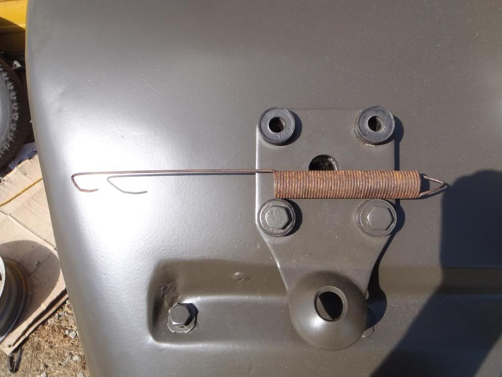
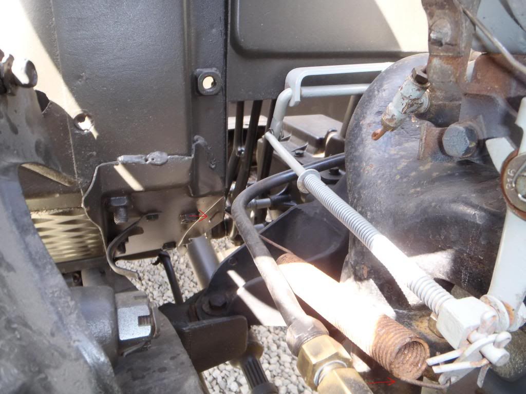
Its been over 30 years since I did this kind of stuff. Had to get tooled up again. This is a fuel line patch I made up to replace the nasty fuel line patch from the PO.


Image
My little patch installed. I think this is where the primer pump was plumbed in originally. When we got the truck there was foot long pipes coming off these and a big 'ol rubber loop tying them together.


Image
Why is everything so hard? Put the thermostat on and the bolts bottomed out. Pulled it all apart again and re-tapped the holes.


Image
A fine example of the state of the original fasteners.


Image
Some of the better fasteners. These lived drenched in dripping engine oil so they survived the ravages of time better.


Image
I've finally given up on the old hardware. I've started taking the screws, nuts & bolts to the store, then buy a sack of each. Slowly the inventory is building up. But things sure do fit together better now!


Image
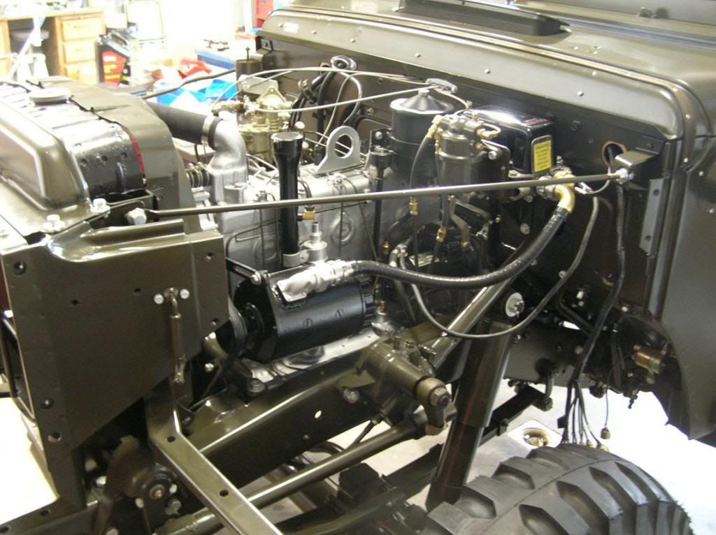
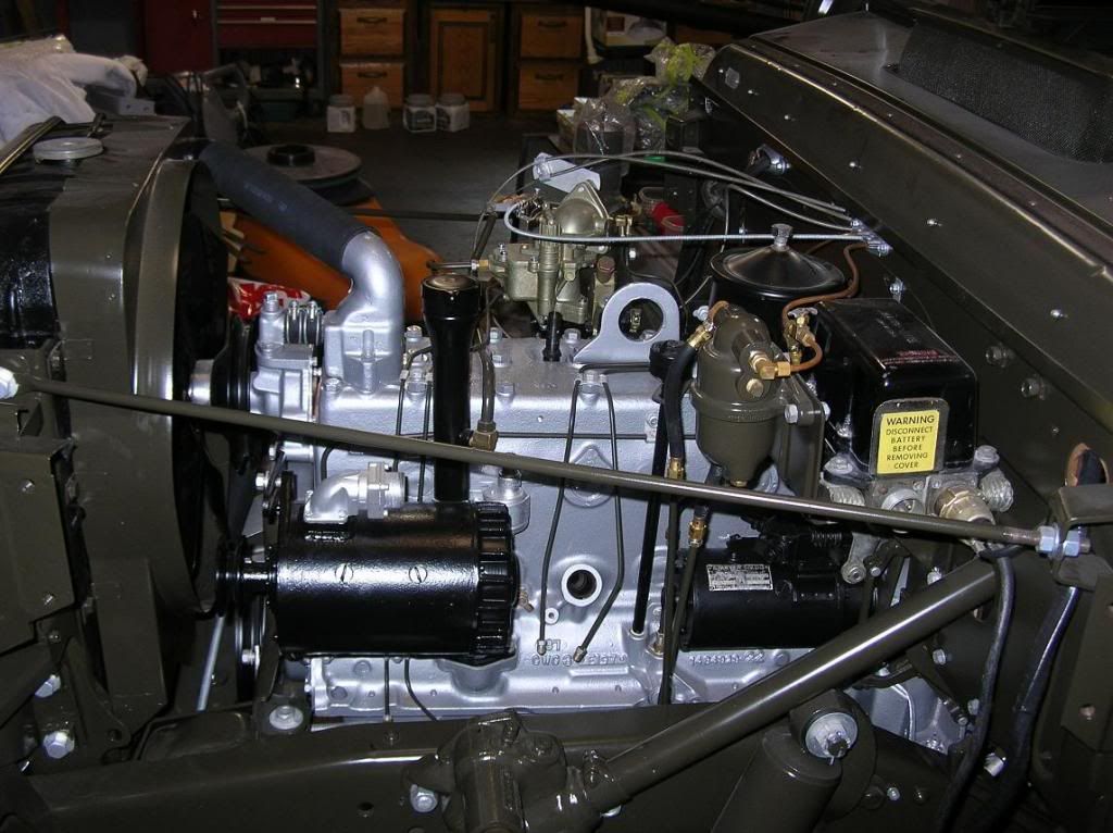
Finally! The thermostat thing is all installed.

Housing!

I've been thinking about why this is taking so bloody long. Much of the time is spent tooling up and getting parts. I'll spend a week waiting for some part or tool then be able to move forward one little step. Then its back to ordering & purchasing for the next step. On top of that, every part seems to want some special attention. Clearing threads, removing broken studs, flattening surfaces. It seems closer to building an engine by hand than slapping together something like a Small Block Chevy.

Anyway, that's where we are now. I ordered the manifold fasteners from MSeriesRebuild. Of the four I had three and one of my brass washers was cracked in half.

Also just ordered another bunch of stuff from Midwest Military.

Fuel filters, Before or after the fuel pump and why? I tend to think before, but lets see what you all come up with.

-jim lee
MSeriesRebuild
1SG
1SG
Posts: 2832
Joined: Sat Oct 20, 2007 4:35 am
Location: Norwood, NC
Contact:

Re: Low compression

Post by MSeriesRebuild »

Jim, you made mention of how long this was taking; I never built one that was not that way. If you don't check and recheck every last detail, you will wind up unhappy or worse. There is always broken bolts to deal with, generally not too bad, but when the person who worked on it before you broke a drill bit or tap off in the hole and left it; well then you have untold hours of time in getting that out usually. People ask me all the time, how come so much time is involved in building these engines to the best one can be? Most never understand that until they have been through one the right way.

Concerning your intake/exhaust manifold installation; here is some good advice; if you haven't already done so, remove all the studs, chase the threads, go back with the correct length new grade 8 studs, use high temp thread sealer liberally on the threads that screw into the block. Several of the holes are through holes into the water jacket, if these are not well sealed, coolant will leak.

Personally, I like a filter before and after the fuel pump. Reason is the one before traps any rust or other debris in the tank and lines from making to the pump where it damages the one way check valves. The one after the pump keeps debris from a deteriorating diaphragm out of the carb bowl where it clogs small passages. Correct, compatible fuel pump diaphragms should not be producing debris, however we find it in carbs all to often.
Charles Talbert
www.mseriesrebuild.com
jim lee
SSGT
SSGT
Posts: 453
Joined: Sat Oct 13, 2012 6:51 pm
Location: Anacortes, WA
Contact:

Re: Low compression

Post by jim lee »

Thanks for the note MSR,

Another question for everyone. Seeing that my distributor is a nasty mess and all, I'm rebuilding it. But, how does one pull the shaft out of the casing? It looks like there's a collar on the shaft with a pin through it locking locking everything together. But in my machine, maybe common? Both ends of the pin are peened over. What do people usually do here?

Do you grind off one end of the pin?

Thanks!

-jim lee
MSeriesRebuild
1SG
1SG
Posts: 2832
Joined: Sat Oct 20, 2007 4:35 am
Location: Norwood, NC
Contact:

Re: Low compression

Post by MSeriesRebuild »

jim lee wrote:Thanks for the note MSR,

Another question for everyone. Seeing that my distributor is a nasty mess and all, I'm rebuilding it. But, how does one pull the shaft out of the casing? It looks like there's a collar on the shaft with a pin through it locking locking everything together. But in my machine, maybe common? Both ends of the pin are peened over. What do people usually do here?

Do you grind off one end of the pin?

Thanks!

-jim lee
Yes you are correct; grind (or file) the end off the .125" diameter pin being very careful not to damage the collar. Drive it out with a small punch. There will be shims beneath the collar that control shaft end play. There will be a larger thrust washer inside the housing just beneath the timing advance weight assembly. Lots of times end play will be excessive, so having extra shims on hand to get that right during reassembly is a good idea. There is 2 bushings, new ones must be reamed or honed to an ID of .501" for the shaft to fit correctly as new. The top bushing has to have an oil wick slot cut as well, the bottom bushing needs a .125" oil hole drilled. Don't forget the oil seal at the top of the shaft bushing bore. We have all the parts on hand; also offer rebuild service if needed. Electronic ignition is a nice upgrade too, easily installed during a rebuild. Does away with points and condenser, and the periodic maintenance required when points are used. If radio interference suppression is not an issue, I'd recommend removing the ignition filter (or capacitor) from the unit if your distributor is the later style. It won't serve any purpose, and is one less component to cause problems down the road. Install a 14 gauge wire from the positive coil terminal routed out through the unit cannon plug connector where it will connect to wire #12 going to the ignition switch. If yours is the early style, the filter will not be there as they were externally mounted on the firewall.
Charles Talbert
www.mseriesrebuild.com
jim lee
SSGT
SSGT
Posts: 453
Joined: Sat Oct 13, 2012 6:51 pm
Location: Anacortes, WA
Contact:

Re: Low compression

Post by jim lee »

Another update..

Image
Kit of shiny new fasteners for holding on the manifolds. Ordered this from MSeriesRebuild. Thanks! They arrived just in time.


Image
Manifold is finally installed. Once you look at the fastener kit and the manifold, the different bits all make sense.


Image
Teaching the kiddies how to create cutom tubing things. Like fuel lines. In fact, they are making fuel lines.


Image
Setting up for flaring the tube for a pipe firing.


Image
Ha! Harder than it looks.


Image
Original setup on the truck. I figured this with its valves and hand bent tubes was too complicated.


Image
My new simpler setup.


Image
The fuel line from the fuel pump to the carb. This is the one the kids made.


Image
Trying to figure out and reassemble the overly complicated throttle linkage.


Image
Meanwile, back at the clean/repair table.. Pulling the distributor apart. We also have an extra for parts. And that's a good thing! This one has some iffy bits. The shaft is held in with a pin that was peened over on both sides. The "spare" distributer has a roll pin holding in the shaft. This is more like what I'd expected.

The engine stand came back and it was built backwards. (Whoops!) The fabricator was might embarrassed. Oh well, hopefully by next time it'll be right and then I'll post a picture.

So, I'm taking heat about installing the clear plastic fuel filters. They'll melt, the car will burn and you'll die! What's everyone's take on these? I wanted to be able to keep an eye on what, where and how much junk is trying to go through the fuel lines.

-jim lee
tbone1004
SSGT
SSGT
Posts: 279
Joined: Sun Mar 17, 2013 10:01 am
Location: Litchfield, ME

Re: Low compression

Post by tbone1004 »

Depends on the heat rating of that plastic. I haven't taken an IR gun to my exhaust manifold, but it is not abnormal for exhaust manifolds to reach 800f+. It is probably a hair lower since the compression ratios in these engines are fairly low, I'm travelling this week so can't start mine up and see what mine is reading with an IR gun, but someone else might be able to or know off the top of their head. Anyway, I work with heat and polymers every day for work designing performance aerospace and ballistic fabrics. My biggest concern with that setup, is that you will be exposing a large volume of gasoline to high temperatures and the inside of that filter is only going to create an oven with the plastic. Does the fuel filter have a temperature rating on the box anywhere?

If it were me plumbing the fuel line, I would have put the filter as close to the gas tank as possible and at one of the lowest points of the system. Sure it wouldn't be as easily visible as under the hood, but then if something happens and clogs your gas lines you're only going to have to replace a few feet of gas line as opposed to potentially having to redo the whole thing. With a fresh tank and lines it obviously isn't nearly as concerning as on older lines/tank but I would still prefer to have it closer to the tank just in case something got through.
MSeriesRebuild
1SG
1SG
Posts: 2832
Joined: Sat Oct 20, 2007 4:35 am
Location: Norwood, NC
Contact:

Re: Low compression

Post by MSeriesRebuild »

That plastic filter and the heat situation is a big deal. I'd never install one that close, certainly could be a fire hazard. The plastic could melt releasing fuel, or a leak elsewhere could happen spraying gas on the hot manifold. Too many risk in my mind.

The next issue that comes to mind is vapor locking. It is absolutely a proven fact that lines and filters need to be as far away from the manifold as possible. We pull all our metal tubing through fiberglass sleeve material, it insulates it from around 1,200 degrees.
Charles Talbert
www.mseriesrebuild.com
jim lee
SSGT
SSGT
Posts: 453
Joined: Sat Oct 13, 2012 6:51 pm
Location: Anacortes, WA
Contact:

Re: Low compression

Post by jim lee »

What are people using for their throttle return spring? I don't see one on here, have no recall of pulling it off and certainly can't find it. Most pictures I see don't show one. Anyone have a snapshot of a throttle return spring? I'd love to see how it looks & hooks up.

Also, the bolt that holds the crankcase vent cap. (behind and under the manifolds) How does this seal? I have a gasket for the cap itself, where it sits against the block, but no idea on how the bolt head seals. I was thinking about getting a copper crush washer and using that.

-jim lee
User avatar
RMS
MSGT
MSGT
Posts: 930
Joined: Tue Apr 03, 2012 2:18 pm
Location: Richmond BC Canada

Re: Low compression

Post by RMS »

I used a copper washer to help seal the bolt on the pvc. I think this is a stock spring for the throttle, three of my trucks have it? And this is were its connected Image
Image
Image
.............................. use it ...............
MSeriesRebuild
1SG
1SG
Posts: 2832
Joined: Sat Oct 20, 2007 4:35 am
Location: Norwood, NC
Contact:

Re: Low compression

Post by MSeriesRebuild »

If you have an overhaul gasket set, the fiber seal washer for the bolt head should be in that. There is a buna-n rubber seal for the cap itself also if you have the complete kit. Nothing else holds up well in an oily environment except for buna-n material.
Charles Talbert
www.mseriesrebuild.com
jim lee
SSGT
SSGT
Posts: 453
Joined: Sat Oct 13, 2012 6:51 pm
Location: Anacortes, WA
Contact:

Re: Low compression

Post by jim lee »

RMS: Thanks for the pix!! I got a copper crush washer and sanded the face of the casting a little smoother. I'm going to check the local part store for a throttle spring.

MSeries : Have the kit, but the gasket that fits is a standard paper one. Nothing that'll fit the bolt. My engine builder may have used it elsewhere? I may be able to get an O-ring to fit though.

Now, how about the tube from the intake manifold to the oil fill tube? This one has me completely stumped. What's it for? I already have a fancy PCV system with shutoff valve etc. Why this second vent and, why is it so large? I'm tooled up for up to 3/8" tube and this is a tad larger. You think the motor would care if it was dropped down to 3/8"?

Thanks again for all the replies. This machine is always proving to be way more confusing than I'd expected.

-jim lee
MSeriesRebuild
1SG
1SG
Posts: 2832
Joined: Sat Oct 20, 2007 4:35 am
Location: Norwood, NC
Contact:

Re: Low compression

Post by MSeriesRebuild »

There is no chamfer for an o-ring to fit into and seal, so that will not be a good choice. I have seen lesser quality kits that didn't use a buna-n (nitrile rubber) seal, you may want to seek out some buna-n material and cut your own. I'd also cut one for the bolt.

If you omit the tube, you will have a healthy rear main oil seal leak as pressure will build. Seen that many times. I would stay with the correct size, it is important.
Charles Talbert
www.mseriesrebuild.com
jim lee
SSGT
SSGT
Posts: 453
Joined: Sat Oct 13, 2012 6:51 pm
Location: Anacortes, WA
Contact:

Re: Low compression

Post by jim lee »

Few more pictures.. Got the kids working for a day.

Image
Oldest daughter ripping the wiring out of the cab. She did most of the behind the dash wiring and Dan did most of the section from the tail lights forward.


Image
The new blinker box. Where do people mount these? Behind the dash? On the firewall in the engine compartment?


Image
More stuff being added to the engine. About 1/2 way through doing the plumbing. Reused the old vent tube from the oil fill to the intake. I don't have any tools to work with 7/16" tube. Never even seen any actually..


Image
Oil fill pipe is finally back on. Had to wash the bead blasting sand out of it. Heard back from the auto/electric guy today. Said that the starter & generator were both in great shape. He's replaced the bearings and is getting ready to reassemble them. Promises them back in a couple days.


Image
Yet more new parts.


Image
First piece of new wiring to go back in. Ground spider on the instrument cluster. Question here. What's the deal with all the plugins behind the instrument cluster? What are they all there for?


Image
Does anyone have a spout for these? I can not believe that they have all disappeared. What happened to them all?


Image
My failed tabletop engine stand. I told them to subtract 3 1/2" from the front legs instead of ADD 3 1/2" to them. Whoops! Anyway its getting re-welded and should be ready in a day or so.


Image
New vacuum lines. Having all sorts of fun making up all these lines. Tricky to get right and easy to mess up at the last step.


Image
Fuel pump all plumbed in. ( Fingers crossed )

We managed to pull the rear wire harness out, in chunks.. I'm not sure how were going to thread the new harness back in there. This started an entire sub project with the tail lights. One had at one point filled with water. Its kinda' a mess inside. The other, the bracket it was attached to had the mounting holes drilled off a little. So, instead of fixing the problem they just put the bolt in at about a 30 degree angle and drove it into the aluminum casing.

Both have had their connectors chopped off some time in the past.

Lovely..

Anyway, that's where the project sits today.

-jim lee
MSeriesRebuild
1SG
1SG
Posts: 2832
Joined: Sat Oct 20, 2007 4:35 am
Location: Norwood, NC
Contact:

Re: Low compression

Post by MSeriesRebuild »

Just a suggestion based on experience. The mil spec flasher you have pictured; they do not have a good track record for longevity at all. May last a week, a month, but at any rate, not likely to live for long. Better option is to get a signal stat flasher from NAPA or CARQUEST, wire in a plug in socket for it and go. They will last for years. We never use the new mil spec ones any more, all imports, and basically junk.
Charles Talbert
www.mseriesrebuild.com
jim lee
SSGT
SSGT
Posts: 453
Joined: Sat Oct 13, 2012 6:51 pm
Location: Anacortes, WA
Contact:

Re: Low compression

Post by jim lee »

52 M-42 wrote:The original engine from the factory was silver. Replacement engines were the same color as the truck. Since it is your truck, you get to paint it whatever color you want.

I've attached a couple of pictures of my engine so you can see what a silver engine looks like. I painted mine silver because I tried to "remanufacture" my truck as new from the factory with a 0 mileage reading.


Image

Image
52 M-42, Do you have any more pix of the oil line plumbing on your machine? I'm at the stage where I'm building this and it would be nice to see some examples to follow.

-jim lee
Post Reply