

 Home
Home 
Hi Jim,
What particular oil lines are you looking for? Vent lines? I can take any pictures you want if you let me know what you want to see.
Are you going to be around Labor Day weekend? Maybe I'll drive the truck up and you can crawl around and look at whatever you want.
PM me and I'll send you my email and phone number.
52 M-42
Low compression
Moderators: Cal_Gary, T. Highway, Monkey Man, robi

Re: Low compression
The lines for the oil filter. How and where they hook to the block. And the can thing. Then, of course the vent lines. I know where the two front ones go. These are the ones that go under the generator, but the other two? Are they the ones that hook to the distributor?
As for numbers, anyone that wants to see this or get in touch with me. http://www.leftcoast.biz/iWeb/Left_Coast/Contact.html
That's where I am nearly every afternoon working on the truck. The phone number is my cell so its good most times. Don't worry about calling at odd hours. I don't have to answer it.
I think getting together and seeing your machine would be great fun! I'm afraid to show you mine. Its no, shall we say.. Pristine?'
-jim lee
Carryall WC53 Blog : https://www.eskimo.com/~jimlee/Home/Car ... _Blog.html
Re: Low compression
Replying to myself. This is sad.
Here's couple concerns I have.
First

WHat sets the distance between the front engine mount and the crank pulley? It looks to me like the crank pulley is too far set in. It looks like it doesn't even line up with the water pump pulley very well either. Is there a shim or something I'm missing? I can't find anything like it in the book.
Second

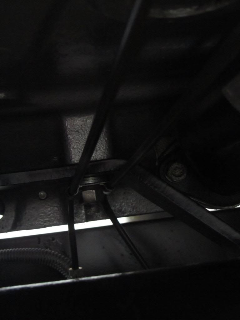
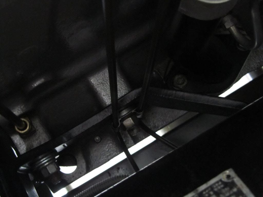
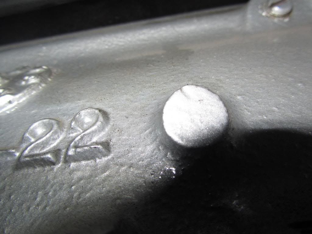
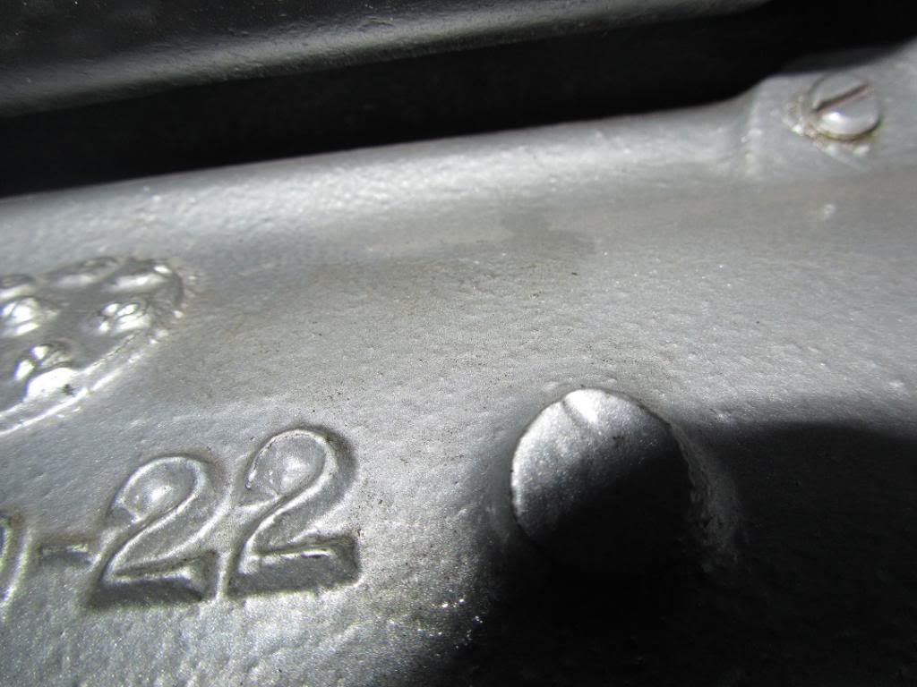
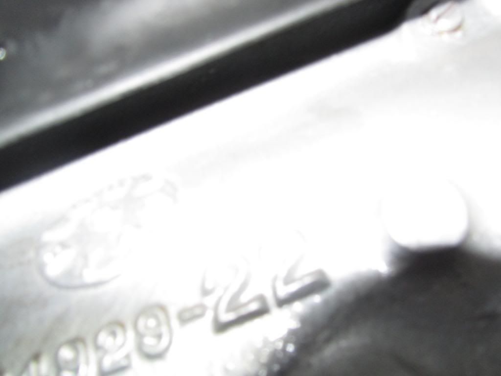
The hole behind the casting number. It goes into the block. I can blow air into it. I don't see any threads. And it looks like other 230 blocks have this sealed over. In fact, it looks like, from my early blurry pictures, that this may have been originally sealed on this engine. Anyone seen anything like this before?
Thanks!
-jim lee
Here's couple concerns I have.
First
WHat sets the distance between the front engine mount and the crank pulley? It looks to me like the crank pulley is too far set in. It looks like it doesn't even line up with the water pump pulley very well either. Is there a shim or something I'm missing? I can't find anything like it in the book.
Second
The hole behind the casting number. It goes into the block. I can blow air into it. I don't see any threads. And it looks like other 230 blocks have this sealed over. In fact, it looks like, from my early blurry pictures, that this may have been originally sealed on this engine. Anyone seen anything like this before?
Thanks!
-jim lee
Carryall WC53 Blog : https://www.eskimo.com/~jimlee/Home/Car ... _Blog.html
Re: Low compression
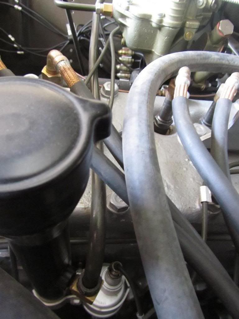
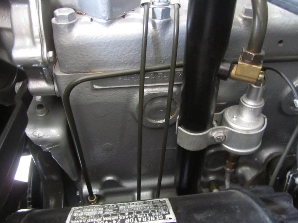
Here are some photos I took today of the areas you wanted to see. I'm sorry some (all) of the photos are a little difficult to comprehend, but the areas you want to see are difficult to get at (lower right side of the engine) or very large and difficult to get detail in a small photo ( this is why you need to see stuff in person). Anyway, here are some photos.
Since my contract in Bellingham ended last Friday, I'll try to bring the truck by one day next week and you can crawl around it and take any pictures you want of stuff.
Since my contract in Bellingham ended last Friday, I'll try to bring the truck by one day next week and you can crawl around it and take any pictures you want of stuff.


Re: Low compression
Hey thanks for the pix!
And, that would be cool if you came by. Just follow highway 20 'till you hit the Chevy dealer on your left. Drive around behind them and there we are. If you come by, I'll buy cheese burgers!
I'm down to two vent lines left to make. Then finish rebuilding the distributer. The kids got the rear wire harness changed out, but I've not checked it. Its getting close to the time to put the motor back in.
-jim lee
Carryall WC53 Blog : https://www.eskimo.com/~jimlee/Home/Car ... _Blog.html
-
T. Highway
- Moderator

- Posts: 1793
- Joined: Thu Jul 09, 2009 4:57 am
- Location: S.E. Wisconsin, USA, Earth
Re: Low compression
JimLee,
The front engine mount looks about right. When you put the engine back in the frame the gap opens up.
Your comment on the water pump pulley not matching up seems odd. I would double check that the hub is in the correct location on the water pump shaft. Did you remember to remove the rear cover of the water pump and seal it before you installed it?
The shaft length / hub was different on my new pump when I compared it to the old one. I turned the bushing (spacer) down on the front of the pulley only to get the fan to center on the water pump hub. Don't rely on the bolts to center it out because this ruin your pump in short order.
Bert
1952 M37 W/W Rebuild @ 59% complete
Engine rebuild @ 95% complete
1985 M1009, 1990 M101A2, 2008 M116A3 Pioneer tool trailer
MVPA # 24265
NRA Life Member
NRA Cert. Personal Protection Pistol Instructor
NRA Cert. RSO
Class III RSO/KCR
Engine rebuild @ 95% complete
1985 M1009, 1990 M101A2, 2008 M116A3 Pioneer tool trailer
MVPA # 24265
NRA Life Member
NRA Cert. Personal Protection Pistol Instructor
NRA Cert. RSO
Class III RSO/KCR
-
MSeriesRebuild
- 1SG

- Posts: 2832
- Joined: Sat Oct 20, 2007 4:35 am
- Location: Norwood, NC
- Contact:
Re: Low compression
You might want to address repair of the hole in the block prior to installing the engine. Getting the cart before the horse never works out just right.jim lee wrote:Hey thanks for the pix!
And, that would be cool if you came by. Just follow highway 20 'till you hit the Chevy dealer on your left. Drive around behind them and there we are. If you come by, I'll buy cheese burgers!
I'm down to two vent lines left to make. Then finish rebuilding the distributer. The kids got the rear wire harness changed out, but I've not checked it. Its getting close to the time to put the motor back in.
-jim lee
Charles Talbert
www.mseriesrebuild.com
www.mseriesrebuild.com
Re: Low compression
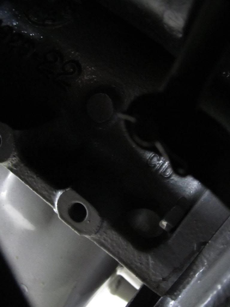
I tried to get some pictures of the engine block area at the lower right rear (the last 4 pictures). They were taken "blind" (that is a tough area to access when the engine is in the truck), so they are not very clear. The boss you have the hole in is solid on my engine, so you will have to plug that hole as Charles mentioned.
Good Luck, and I'll try to come by Tuesday or Wednesday of this week.
52 M-42
Good Luck, and I'll try to come by Tuesday or Wednesday of this week.
52 M-42
Re: Low compression
Thanks guys. I drilled out the hole, tapped it 1/8 NPT and put in a pipe plug. That should put an end to it.
As for the water pump and fan.. I didn't install the pump, so I'm not sure how it was done. If it was in "the book" it was probably done that way. He followed the book pretty close from what I saw. I'll wait 'till the generator is installed to see what 2 our of 3 pulleys line up. Then it'll be more clear on what to do.
Thanks again for the comments. They help a lot.
-jim lee
Carryall WC53 Blog : https://www.eskimo.com/~jimlee/Home/Car ... _Blog.html


Re: Low compression
it sure looks like the pulley is in too far to me, as the timing mark is sticking out past the pulley. im not aware of any oil slinger washer or spacer that fits between the timing gear and the pulley boss. were all three parts of the pulley used? was the .040 felt holder omitted ? not that the felt holder alone would make up the difference between the edge of the pulley and the timing mark. I compared the height of a mill pulley to a civy pulley and there is a big difference. if the gen pulley lines up with the crank pulley i would suspect that your timing cover was swapped out for a civy one........ hummm was the military timing set replaced with a civilian one? there is .010 difference between the two but i dont think that would make up the difference. now i did not see any mention of an oil slinger in the book but in one of my engine totes I did find a oil slinger that is .080. Could a civy timing set .010 + felt holder .040 + oil slinger .080 make up the difference ?jim lee wrote: -jim leejim lee wrote:Replying to myself. This is sad.
WHat sets the distance between the front engine mount and the crank pulley? It looks to me like the crank pulley is too far set in. It looks like it doesn't even line up with the water pump pulley very well either. Is there a shim or something I'm missing? I can't find anything like it in the book. -jim lee


.............................. use it ...............
Re: Low compression
Some more pix..

Remember from earlier,I said SUBTRACT 3 1/2" from the front mounts instead of ADD 3 1/2" to them. Caused a lot of wasted effort and I felt dumb. Don't do do engineering when in a tremendous hurry.

Alls well that ends well.. Mount fixed. It fits ok. I'd assumed the bolt pattern would be a rectangle. I'm thinking it may not be now..

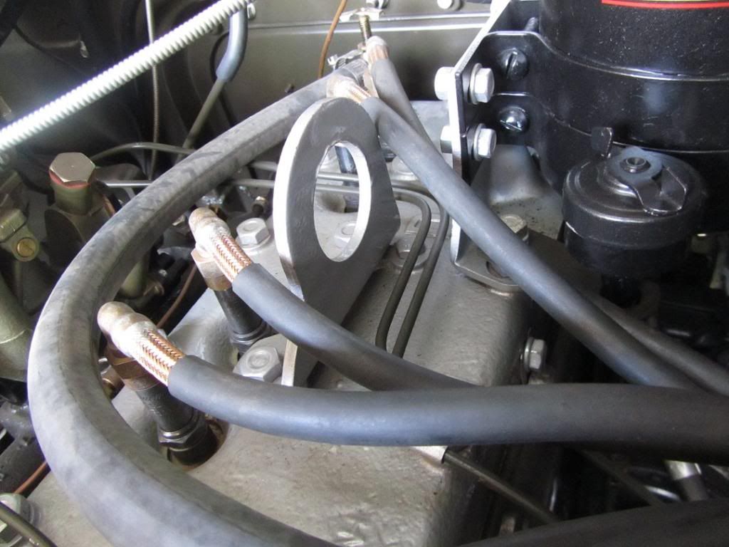
Daughter test fitting her oil line. She keeps getting the short end of the stick in this project. I can only manage about 2 kids at a time and the older ones are easier. I heard her saying she liked making up the lines, so I took her to the shop by herself and we made lines.

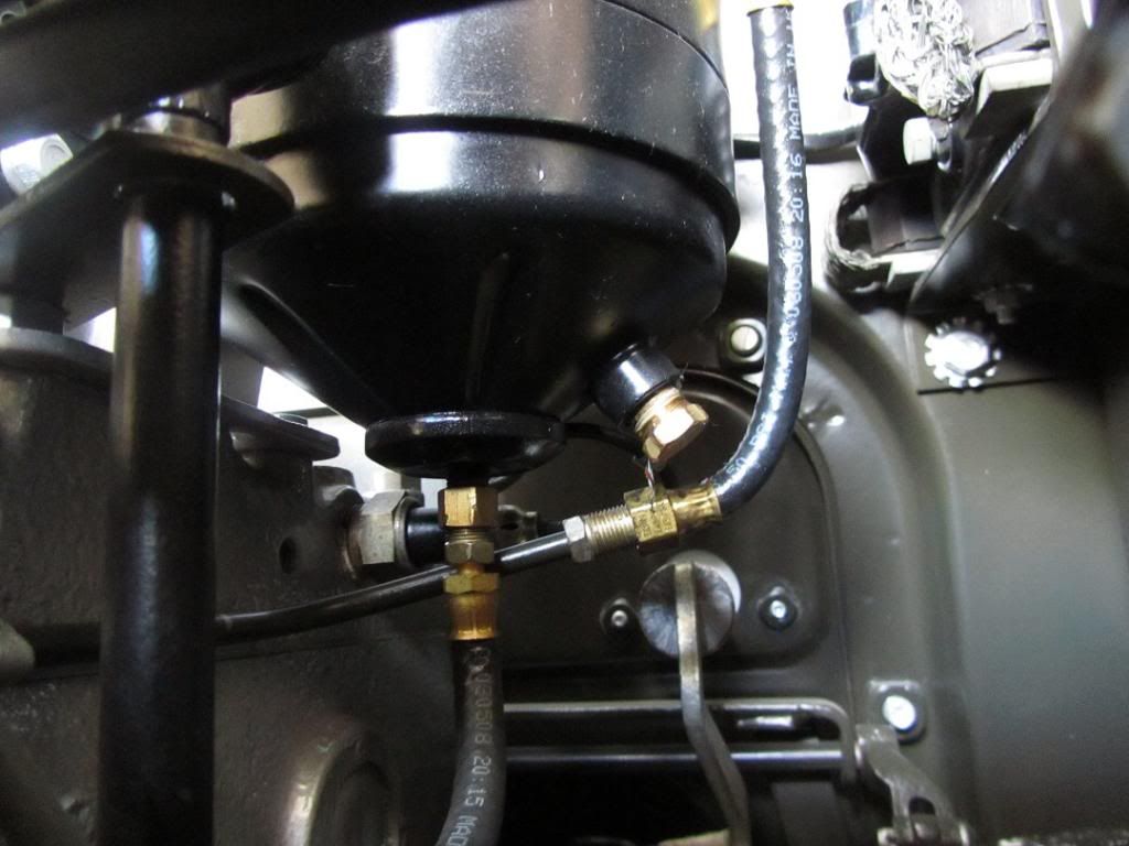
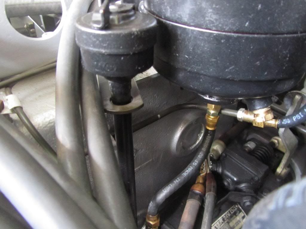
Planning the oil filter feed line.. Or drain? No.. I think it feeds in the bottom and drains at the top.

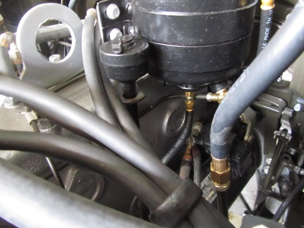
Oil filter is all plumbed in!

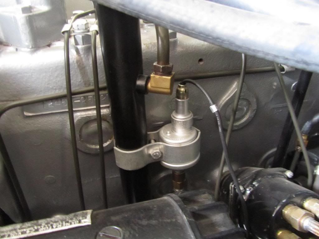
I did the fwd vent lines. Brake master cylinder & fuel tank. These are the two that end up under the generator. The crankcase vent was a bizarre 7/16" line so I just cleaned the old one and put it back.

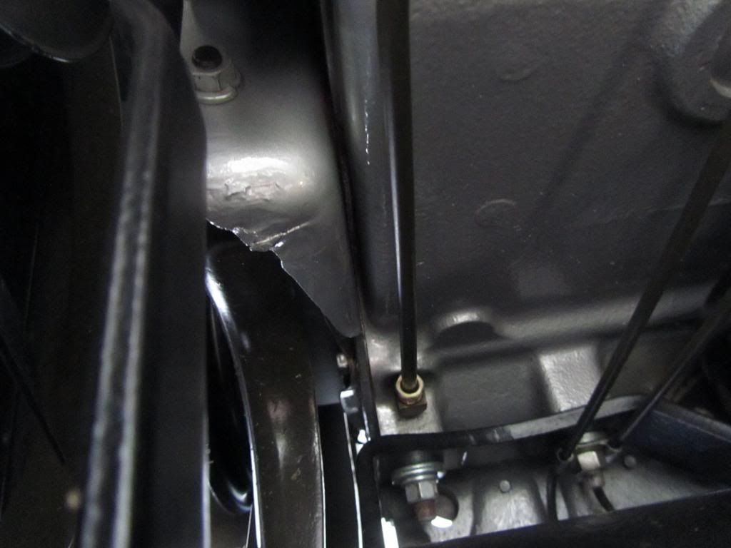
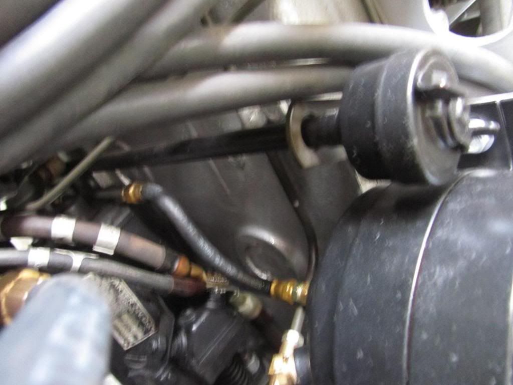
Vent lines & oil filter complete. If you look close at the bottom rear of the block you can see the mystery hole is drilled, tapped and a 1/8" NPT pipe plug is in there.

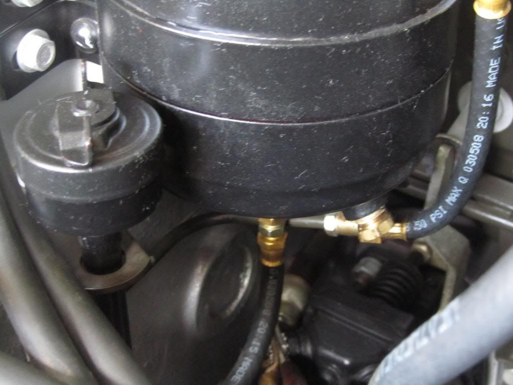
For the ongoing "will the fuel filter melt?" issue.. This is how far it is from the exhaust manifold.
Thats where things sit tonight. I need to make up the distributer vent lines and finish up rebuilding the distributer. Also I need to figure out how the plate and seal go on between the oil pan and the flywheel. That seal is a mystery to me. How does it goes in there and what holds it from falling out?
-jim lee
Remember from earlier,I said SUBTRACT 3 1/2" from the front mounts instead of ADD 3 1/2" to them. Caused a lot of wasted effort and I felt dumb. Don't do do engineering when in a tremendous hurry.
Alls well that ends well.. Mount fixed. It fits ok. I'd assumed the bolt pattern would be a rectangle. I'm thinking it may not be now..
Daughter test fitting her oil line. She keeps getting the short end of the stick in this project. I can only manage about 2 kids at a time and the older ones are easier. I heard her saying she liked making up the lines, so I took her to the shop by herself and we made lines.
Planning the oil filter feed line.. Or drain? No.. I think it feeds in the bottom and drains at the top.
Oil filter is all plumbed in!
I did the fwd vent lines. Brake master cylinder & fuel tank. These are the two that end up under the generator. The crankcase vent was a bizarre 7/16" line so I just cleaned the old one and put it back.
Vent lines & oil filter complete. If you look close at the bottom rear of the block you can see the mystery hole is drilled, tapped and a 1/8" NPT pipe plug is in there.
For the ongoing "will the fuel filter melt?" issue.. This is how far it is from the exhaust manifold.
Thats where things sit tonight. I need to make up the distributer vent lines and finish up rebuilding the distributer. Also I need to figure out how the plate and seal go on between the oil pan and the flywheel. That seal is a mystery to me. How does it goes in there and what holds it from falling out?
-jim lee
Carryall WC53 Blog : https://www.eskimo.com/~jimlee/Home/Car ... _Blog.html
-
MSeriesRebuild
- 1SG
- Posts: 2832
- Joined: Sat Oct 20, 2007 4:35 am
- Location: Norwood, NC
- Contact:
Re: Low compression
Not sure, looks like push-lock hose and fittings used on the oil filter. I have seen these come apart a few times in some past applications, thus I never trust them in such critical areas as oil pressure lines. A slip up here and oil could be dumped and engine blown before you ever realize what is happening. We always use hoses here with crimped on fittings, not worth the risk using push lock in my mind. I have seen people use them for fuel lines also, the manufacturer even recommends against that.
Charles Talbert
www.mseriesrebuild.com
www.mseriesrebuild.com
Re: Low compression
I still wouldn't put that filter there... It's still too close. That manifold well get well up over 500F when it is running and that is just asking for vapor lock, or potentially a melted filter... I'd either move it down as low as possible so the heat shield for the pump can at least try to protect it, or move it to inside the frame rail and just take a look underneath the truck on a regular basis. At least that way you're not putting whatever contaminants through the fuel pump which could wreak havoc on the diaphragms.
-
T. Highway
- Moderator
- Posts: 1793
- Joined: Thu Jul 09, 2009 4:57 am
- Location: S.E. Wisconsin, USA, Earth
Re: Low compression
Jim Lee,
The part number for the oil line is 11224 @ NAPA. This line can also be found at a Eaton/Weatherhead dealers also, it's known as a Air Brake Chamber / Drop Down Hose.
If this is the seal you are talking about it is held by bolts.

Bert
The part number for the oil line is 11224 @ NAPA. This line can also be found at a Eaton/Weatherhead dealers also, it's known as a Air Brake Chamber / Drop Down Hose.
If this is the seal you are talking about it is held by bolts.
Bert
1952 M37 W/W Rebuild @ 59% complete
Engine rebuild @ 95% complete
1985 M1009, 1990 M101A2, 2008 M116A3 Pioneer tool trailer
MVPA # 24265
NRA Life Member
NRA Cert. Personal Protection Pistol Instructor
NRA Cert. RSO
Class III RSO/KCR
Engine rebuild @ 95% complete
1985 M1009, 1990 M101A2, 2008 M116A3 Pioneer tool trailer
MVPA # 24265
NRA Life Member
NRA Cert. Personal Protection Pistol Instructor
NRA Cert. RSO
Class III RSO/KCR
-
MSeriesRebuild
- 1SG
- Posts: 2832
- Joined: Sat Oct 20, 2007 4:35 am
- Location: Norwood, NC
- Contact:
Re: Low compression
NAPA has these hoses on the endangered species list now. They are only available from Eaton these days. They are actually fuel lines for vintage autos according to Eaton literature. We have gotten them several years through CARQUEST. Same source for the larger 5/16 hose that supplies the fuel pump, seems the # for it is 1187 if memory is correct, (long shot there). We have a really good CARQUEST source that replaced our NAPA locally, they can get a lot more stuff than NAPA ever cared too. NAPA is more tied to their specific suppliers which do not offer lots of items that once were common place. Car Quest will source it from where ever they have too.T. Highway wrote:Jim Lee,
The part number for the oil line is 11224 @ NAPA. This line can also be found at a Eaton/Weatherhead dealers also, it's known as a Air Brake Chamber / Drop Down Hose.
If this is the seal you are talking about it is held by bolts.
Bert
Charles Talbert
www.mseriesrebuild.com
www.mseriesrebuild.com