powerwagontim wrote:Hi Charles,
Of the 7 wires, 3 plug directly into the flasher, leaving the 4 that Stu was referring to.
Tim
I'm totally aware of how it works, but that was not his statement. Saying it is a 4-wire would be confusing to those who are not familiar, that was my point.
You are incorrect in saying 3 of the 7 wires hook directly to the flasher. The "A" and "B" wires hook directly to any 2-prong flasher, 12 or 24-volt, while the 3rd (non-lamp) wire is connected to the power output terminal on the brake light switch. This is the lead that enables the brake light function to operate through the signal controller switch, and the function that makes this type switch the superior choice.
1 of those 3 wires from the plug simply goes to ground, the short lead with the eyelet off the military flasher plug, and not back to 1 of the 7 wires, coming from the controller.
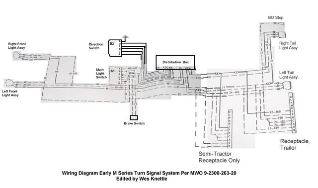
The military solid-state flasher requires a ground. If you are using a conventional type electro-mechanical or all electronic flasher as is shown in figure "A" that Cuz posted; those flashers do not have a ground lead connected. The 3rd prong of the flasher labeled "P" powers the pilot indicator bulb, that is an integral component within the 900 series controller. With 3-prong flashers, the terminals are marked "X" which is a fused line that inputs power into the flasher, "L" or load, which is the lead that inputs power into the controller, and "P" that activates the pilot bulb function. A 2-prong flasher only offers the "X" and "L" function and is used with controllers that either do not have an integral pilot lamp, or the pilot lamp is powered from another source such as the 905 series. On the 905 series controller, the "P" wire is eliminated. Neither the 2-prong nor the 3-prong conventional flashers need a ground to operate. The military flasher must be grounded, thus the 3rd lead at the plug. The pilot bulb function within the military switch is powered from internal switch contacts, "P" isn't needed. This is why the military flasher will directly interchange with a standard 2-prong non-grounded flasher. That switch must ground where it is clamped to the steering column jacket or by a separate ground wire between the switch and a remote ground stud. The ground is only for the pilot bulb function, the switch does not have to be grounded in order to operate the system. The diagram for the military switch is the same used in figure "A" with the "P" wire eliminated, except for the 7th wire is power from a fused lead into the system. There is actually only 6-wire contacts at the switch cannon plug, with wire 7 in the harness taking input power directly to the flasher.
These are the basic differences between the mil-spec and the 900 series if my memory hasn't missed a gear as it sometimes tends too.
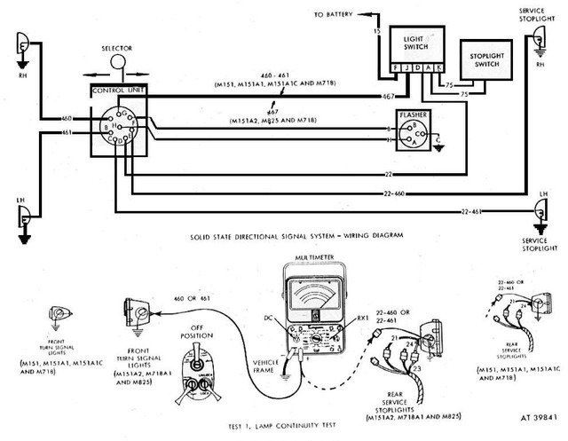
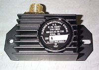
MSeriesRebuild wrote:That switch you have pictured is the military version of the 900 series. Unless it had been altered, there would be 7-wires coming from it.
I altered it by taking it apart and identified the wires/connections that were necessary for it to work in my application.
I only required 4 of the 7 connections.
Cheers
Stu
Stu
1952 Dodge M37 with 1952 M101 Trailer
MVT UK
SMVG Scotland

 Home
Home 


