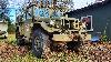
Ralph made this, using stuff he had on hand, to provide oil under pressure for the engine we are rebuilding to install in his truck which will replace the civ. truck engine which we will remove and install in the red 1953 M37W/W I bought from him last week. (pix of my new truck in Webshots album) Yesterday we put the rings on the pistons, installed the cam, valves, crank, ck'd bearing clearances and are ready to install the rest of the stuff next time we get together to work on it. He left for Jamaica today so work has halted until he returns. Questions?
cool,
some details, dimensions, description of components would be great to have if possible. I've thought about getting one for my truck, building my own would be that much better. Thanks
Looks like two regulators in series with a water filter also in series.
The output then feeds the top of the PVC andcompresses the air above
a certain volume of oil.
This is just what I'm gleaning from the pictures.
J.B.
that makes sense
some more questions though:
- Where does it tie in with the existing oil system?
- How is it controlled? Manually or automatically (solenoid maybe?)
- Where is it intended to be located in the vehicle?
- Where does the compressed air come from?
I've looked at these before http://www.accusump.com/
as much as I'd love to make my own, I doubt I could do so for less than these (unless I don't count my time!)
The rig Ralph designed and built uses an external air source, his shop compressor, and only will be used at the time of the rebuilt engines initial start-up and not for everyday driving.
I may be incorrect in describing the components as while he was putting it together, I was busy cleaning up the pistons, installing rings, lapping in the valves and didn't pay much attention to what he used. But, if I have it correct, the 2 pressure regulators are actually a flow volume control (blue) and a regulator. it has a one way check valve and the water/particle filter and a output shutoff. It connects to a pipe T installed at the engine blocks pressure line that feeds the oil filter and is manually controlled. It won't be mounted on the truck but will free stand along side and connect thru hoses to the oil gallery T.
The links below direct you to Doc Dave's posts about a pre luber he designed and built as well as another design built based on his ideas.
monkeymissile wrote:thanks for posting the links, interesting and helpful
You are welcome, I was thinking it might help someone wanting to make their own.
I had seen Doc Dave's post about his luber several years ago and had to search several posts of his going back years to finally locate the one I wanted. I had never thought about prelube until his posts, kept the idea in my mind until needed and told Ralph we should use one when we started his engine for the first time and the design he came up with was all his as he never saw the search results and just figured it out for himself. He is the senior mechanical engineer at Becton-Dickenson a medical supply mfgr. and has a good head for such things.
Carter
Life Member:
Delta, Peach Bottom Fish & Game Assn.
monkeymissile wrote:that's a good kind of friend to have around!
A good friend he is, I've known him for 30 yrs. and he sold me his other complete but dissasembled M37 with a winch for $400. He just doesn't feel like taking the time to restore it and put it back together. I suspect the winch, cable, pto and shaft are worth a lot more than that but don't know what they are bringing these days, but I couldn't pass up a deal like that.
Carter
Life Member:
Delta, Peach Bottom Fish & Game Assn.


 Home
Home

