Page 1 of 1
Slave cable questions
Posted: Sat May 14, 2011 4:51 pm
by powerwagontim
Hi Guys,
Getting ready to install my slave cables. The book gives a written description of the install, I am clear on the ground connection, and it mentions running the pos. cable through the clip at the dimmer switch. OK so far, but thats where the description stops. I know that it ends up at the starter, but want the correct routing path and any other clips or straps between the dimmer switch clip, and tthe starter. I am assuming it goes up over the top of the pedels, but we all know about assumptions!
Also, I need to modify the lengths of the cables on my unit, bought off Ebay new, but meant for something other than an M37. Anyone have the correct lengths of the cables?
Thanks,
Tim
Re: Slave cable questions
Posted: Tue May 17, 2011 2:19 am
by Cal_Gary
Sorry Tim,
Mine had no slave cable so I can't offer a solution. I also have one awaiting install but do not know at this time if the cable lengths are correct.
Gary
Re: Slave cable questions
Posted: Tue May 17, 2011 5:08 am
by ChadNC
Hi Tim and Gary,
I have a new slave cable assembly that I need to install along with my battery cables. Since I have the front tires/fender liners off I will take some measurements and photos tonight - should be able to get some clear pictures that way.
Chad
Re: Slave cable questions
Posted: Tue May 17, 2011 2:10 pm
by powerwagontim
Hi Chad,
Thats great, I really appreciate your efforts. I look forward to seeing what you have.
Apparently, there are numerous cable lengths that come with these fittings, while you are in there, you might want to verify that your new one has the right length cables!
thanks again,
Tim
Re: Slave cable questions
Posted: Tue May 17, 2011 2:57 pm
by MSeriesRebuild
There is no exactly correct way to do this. What matters is that cables are routed away from moving parts, sharp objects, and are clamped securely at good locations. Believe it or not, we have seen where people have tied these cables to the cluch and brake pedal with a zip tie strap; a real sharp thinker for sure. Remember the cable needs some slack also to allow for body and engine movement on rubber mounts. Be CERTAIN the rubber isolators are in place where the cable is routed through holes in the cab tub so it is guarded from sharp edges on the sheet metal.
Another issue we pay special attention too is this; we do not ever bypass the system disconnect switch with a slave cable outlet. If you do, this leaves the door wide open for a very quickly ignited fire if cable damage occured creating a short at any point in time. It is a wise decision to wire it so that the current path is also cut to the slave outlet when your disconnect switch is off. If you don't have a battery disconnect switch; it's a good time to get one.
Re: Slave cable questions
Posted: Wed May 18, 2011 3:56 am
by ChadNC
Hey Guys,
We had a bad lightning storm last night so I wasn't able to get all of the pictures. I'll have them tonight - comments are welcome too as I would hate to screw it up and burn down my hard work.
Length appears correct on the new assembly - it was one of the last things I got from Sid

Re: Slave cable questions
Posted: Wed May 18, 2011 6:32 am
by MSeriesRebuild
ChadNC wrote:Hey Guys,
We had a bad lightning storm last night so I wasn't able to get all of the pictures. I'll have them tonight - comments are welcome too as I would hate to screw it up and burn down my hard work.
Length appears correct on the new assembly - it was one of the last things I got from Sid
Be really careful in looking at the cable insulation. Most of these assemblies, even though they are new are years old in storage. Insulation may look OK, but I've seen many start to crack, etc in a short while after coming out of the sealed package and hitting open air. In fact I have seen this so much that we never use one of these without removing the old cable and replacing with fresh welding cable. It is easy to do, then you can do an installation that will last many years without worry of cable deterioration. Always remember, this is a large cable, it can easily light a fire long before the cable itself will burn in too if it were to get grounded and short out due to bad insulation. Another thing we do is put the cable in poly loom. This adds a great degree of protection and keeps UV rays at bay. Sun light is a huge enemy to the insulation on military wiring. This is another issue where technology has come a long way; you have choices in wire types and insulation today that did not exist back in the day, work smart and get the right material for the job. Doing stuff on the cheap, well you know that drill.
Re: Slave cable questions
Posted: Thu May 19, 2011 4:05 am
by ChadNC
Here are some pictures of the current routing on Ol' Blue...
Back of cable assembly showing short ground lead to running board bracket - as Charles mentions there is also a bushing where the wires come through the hole in the cab tub:
- DSC03505.JPG (217.92 KiB) Viewed 1529 times
Cable routing by the dimmer switch - there is a rubber clamp missing in this location:
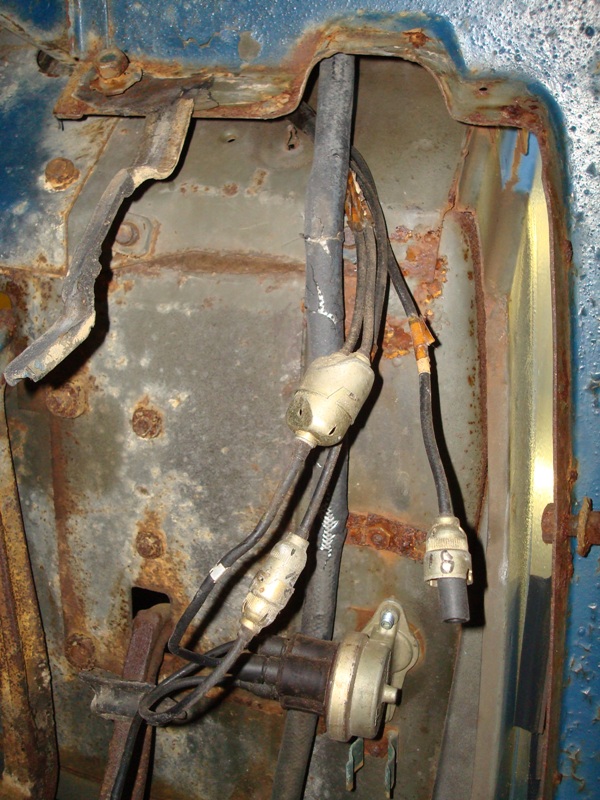
- DSC03504.JPG (211.69 KiB) Viewed 1529 times
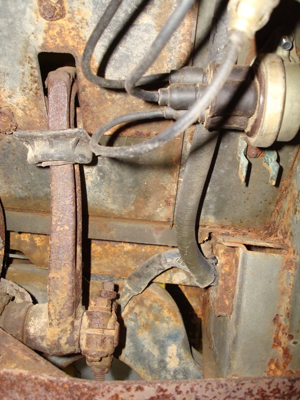
Attachment to the starter:

- DSC03508.JPG (204.94 KiB) Viewed 1529 times
The new assembly has a part number of 8707574 and has ~ 12" of ground lead and ~60" of positive lead. The one I have has a date code of 1970 on it - Charles do you have any tips for separating the pins from the plug assembly for replacing the cable?
Chad
Re: Slave cable questions
Posted: Thu May 19, 2011 6:30 am
by MSeriesRebuild
Secure the assy in a vise. Select a punch that fits snug inside the female terminal, tap both lead terminals out of the rubber insulator. Heat to remove terminal from cable. Thread new cable through the insulator, strip insulation and install terminals by soldering onto cable. Install the terminals back into the insulator in the same manner you removed them. You will feel it when the terminal drops into position in the insulator.
Re: Slave cable questions
Posted: Fri May 20, 2011 3:47 am
by ChadNC
MSeriesRebuild wrote:Secure the assy in a vise. Select a punch that fits snug inside the female terminal, tap both lead terminals out of the rubber insulator. Heat to remove terminal from cable. Thread new cable through the insulator, strip insulation and install terminals by soldering onto cable. Install the terminals back into the insulator in the same manner you removed them. You will feel it when the terminal drops into position in the insulator.
Sounds good Charles - I was hoping that they were a press fit but didn't want to force anything without asking. I appreciate the help.
Chad